Nearly There
No progress last week as I went to Betws-Y-Coed in north Wales for the weekend.
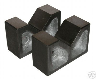
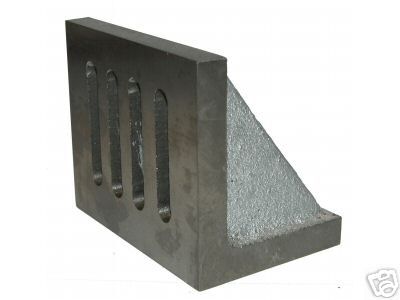
In the meantime, I bought an angle plate and V blocks from ebay - a bit smaller than I wanted with £6 post - but I seem to have been concentrating too much on the Kinglett when it will take too much time, effort and ability that I have.
So spent a couple of hours on the wriring again today, readu to add a mains lead tomorrow. The motor looks out of line for the pulleys, and was difficult to fit with the noew belt, but I think that is because the two pulleys will need realigning when I get it running, hopefully tomorrow.
I gavent sourced a no-volt switch yet and I kind of wish I had kept the steel box I fitted to lathe no 2, and installed the nice forward and reverse switch in it. As is, I will just wire to enable forward for now.
posted by Vincent at 18:59
0 comments
![]()
